RC equipment: Radio
control equipment consists of a transmitter, a receiver, and a number of servos. The
servos are plugged into the receiver with one servo for each controlling channel. The
number of channels used depends on the model itself, for example, a two-channel sailplane
will employ one channel for controlling the rudder and the other for the elevator. The
receiver together with all the servos and the battery are installed on the model aircraft
while the transmitter is carried by the pilot during flight. The pilot controls the
aircraft by moving the sticks or flipping the switches in the transmitter.
Working Principle: Most modern RC equipment are based on proportional control where
the amount of movement applied on the stick in the transmitter is proportional to the
amount of servo's movement in the receiver. All RC equipment are operating on a principle
as similar to broadcast radio. In broadcast radio the audio signal is modulated on a
carrier signal. The frequency of the carrier signal is much higher than the frequency of
the audio baseband signal so that it is easier for the modulated signal to leave the
transmitter's antenna. There are two popular modulation schemes; frequency modulation (FM)
and amplitude modulation (AM). Generally, FM has an advantage over AM in terms of noise
immunity. There is a general misconception that AM and FM transmitters are mutually
interference free. No! this is not the case. Provide that their carrier frequencies are
the same, they will interfere each other. So please check the carrier frequencies of other
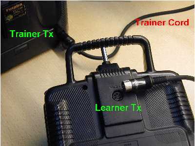
RC pilots nearby before switching on your transmitter! Most RC systems allow you to change
the carrier frequency by replacing the x'tals on both the transmitter and receiver. You
can buy an extra pair of x'tals in case someone is using the same carrier frequency as
yours in the flying site. Note that this matched pair of x'tals consists of a x'tal
for transmitter (typically marked as Tx) and a x'tal for receiver (marked as Rx). The
system does not work if you insert a Rx x'tal in the transmitter or vice versa if you
insert a Tx x'tal in the receiver. Also note that, some receivers utilize dual-conversion
technology, the Rx x'tal used in a dual-conversion receiver is different with the Rx x'tal
used in a single-conversion receiver even their carrier frequency markings are the same.
In radio control systems the baseband signal is a collection of all control
signals each represents a movement of the stick on the transmitter panel. Basically, there
are two popular schemes to represent and to combine those control signals; they are pulse
position modulation (PPM) and pulse code modulation (PCM). Generally, PCM is only
available for FM transmitter while PPM is available for both AM and FM transmitters. In
PPM scheme, the baseband signal is constructed as a sequence of frames. There are about 50
frames per second (so it is no use if you move faster than 20ms!). In each frame, there
are a number of pulses each representing one control channel. The pulse width varies from
1 ms to 2 ms according to the stick position. The pulse width is 1.5 ms if the control
stick is in its neutral position. Therefore, RC equipment can maximally have 8 channels
(note that some PCM systems may have 9 channels due to different coding structure). In PCM
scheme, the range of stick movement is divided into a large number of small quantized
steps. Typically, there are 1024 steps and hence each step can be represented by a 10-bits
code. Totally, all channels of 10-bits codes together with an error check sum are inserted
into the 20 ms frame for transmission. Since PCM scheme has error detection capability
built-in, it has inherent advantage over PPM scheme when there are transmission errors
either being interfered by other RC transmitters or due to lost of transmitter power.
Typically, the PCM receiver will set all servos to default or preset positions when
transmission errors are detected. Again, there is also a general misconception that PPM
and PCM systems are mutually interference free. No! this is not the case either. The cause
of interference is entirely dependent on the carrier frequencies used; check your x'tal
and make sure that there are no more than one transmitter working on the same carrier
frequency!
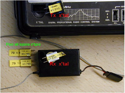
You may change the carrier frequency by replacing a pair of
x'tals both in the transmitter and receiver
Transmitter: Most RC transmitters have two sticks, one on the left and one on
the right. The stick longitudinal and latitudinal movements are related to the controlling
channels as shown in the photo below. With respect to aircraft control, there are two
popular modes of operation that relate the transmitter stick movements with the aircraft
controlling surfaces. They are:
| |
Mode I |
Mode II |
| Channel 1 |
Aileron |
Aileron |
| Channel 2 |
Elevator |
Throttle |
| Channel 3 |
Throttle |
Elevator |
| Channel 4 |
Rudder |
Rudder |
The major difference of flying using these two modes is that you
can control a 2-channel sailplane with only one stick if you use Mode II while you need
two sticks in Mode I. In Hong Kong, most RC pilots fly their aircraft using Mode I.
Some advanced programmable transmitters allow you to set and remember the parameters for a
particular model, for examples, aileron/elevator mixing or flap/elevator mixing. Also
there are factory preset parameters for models such as helicopter, aircraft and/or glider.
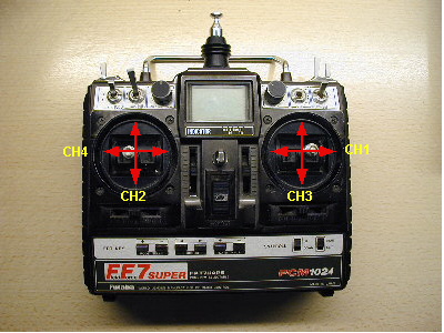
RC transmitter and its channel/stick relationship
Receiver:
The size of the receiver must be small in order to fit into the model. The
size mainly depends on the number of channels available. Also, PCM receivers are typically
bigger than FM or AM receivers. All receivers should have a long cable feed antenna. Mind
you that when you install the receiver on your plane, you have to fully extend the antenna
feed cable in order to achieve maximum transmission range. A receiver has a number of
sockets for the servos to plug-in. There is also a socket for the battery power input. We
normally use NiCad rechargeable batteries for long life and re-usability.
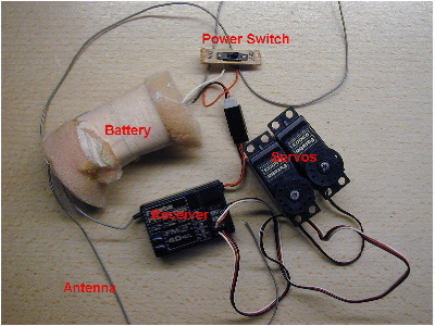
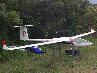
Stuff that is put on the plane
Selection of RC
Equipment: There are a number of R/C equipment manufacturers. The big names are
Futaba, JR, Hitec. There are a number of important factors influencing your choice of RC
equipment. They are:
Cost: Of course, this should be as low as possible,
typically, the cost of RC equipment depends on, the number of available channels, AM or FM
transmitter, PCM or PPM scheme and the functionality of the system. The cheapest systems
are those 2-channel AM systems while the most expensive systems are those 9-channel PCM
systems with programmability.
Number of Channels: It very much depends on the
models you are going to control. Most gliders require 2 channels, more advanced gliders
may require 6 channels. Generally, a 4-channels system, such as Futaba's Skysport 4, is
sufficient for most purposes. However, if you are flying delta wing gliders, you need some
kinds of mixing mechanism, then you might need a more advanced RC system with electronic
mixing in the transmitter, or you might add a mixer (either electronic or mechanical) on
board the aircraft.
Modulation Schemes: AM systems typically operate at
27MHz frequency band and this band is widely used by RC cars and RC boats. The cost of AM
systems is low but AM receiver is most susceptible to noise interference. The FM systems
you can buy in Hong Kong are those that operate in 72MHz, 40/41MHz, 35/36MHz bands. So far
40MHz band is the most populous band in Hong Kong. Some expensive transmitters were
designed to be flexible by using plug-in RF module, for example, Futaba FF7. By changing
the RF module, you can switch to use another frequency band, say, from 40MHz band to
72MHz band. Of course, the frequency of Tx x'tal on the RF module must match to the
frequency of Rx x'tal in the new band in order for the system to function correctly. It is
worth while pointing out that, in order to operate RC equipment in Hong Kong, you need to
use the legal frequencies assigned by the Office of Telecommunications Authority (OFTA).
The 27MHz band, from 26.960MHz to 27.280MHz is opened to public use without the need of a
license, however, it is for CB and other public wireless applications, so it is
generally not suitable for remote control of model aircraft. From April 2005 onward,
OFTA has released a total of 18 new channels for r/c models; 6 channels in the 72MHz band,
8 channels in the 35MHz band and 4 channels are in the 40MHz band. There is no need to
apply for a license to operate on these frequencies. For details, please see the
information in here.
Coding Schemes: PPM is sufficient for most RC flying
activities. Many expensive transmitters have dual PPM and PCM mode in which you can select
either PPM or PCM coding at will. Many people say that PCM system is safer because it has
error locking capability. Well, it depends, sometimes it is better not to lock the
aircraft in case of transmission errors because if the plane is locked and continues to
fly on its current course, it may finally crash in a remote area, for example, the sea,
then you will have a total loss. Nevertheless, if your plane crash nearby in case of
transmission errors, at least, you may be able to recover something! Meanwhile, in case of
transmission errors, you will immediately notice the problem for PPM system, while for PCM
system, the receiver will hide the errors until it is too late for you to react.